Close-In Optical Tracking System

Multispectral Imaging and Tracking System (MITS) Close-In Tracking System
Introduction:
Our Close-In system collects highly accurate Time-Space-Position-Information (TSPI) or Engineering Sequential Data (ESD) from high-dynamic airborne and ground based targets.
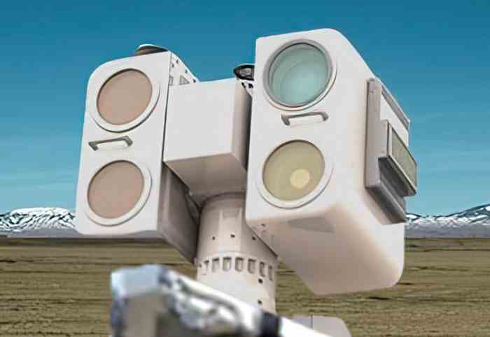
The Close-In gimbal provides up to four sensor stations to be equipped with lightweight sensors and short-range optics and is designed to be positioned in close proximity to either the launch or termination stage of an event.
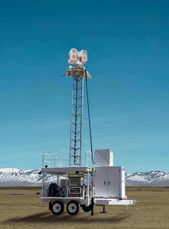
The Close-In gimbal can also be installed on an optional 30-foot telescoping tower to reduce the effects of scintillation on tracked images and to avoid smoke and dust caused by the event (note that dynamic performance and system accuracy may be reduced when the Close-In gimbal is installed on the tower). The Close-In system is highly flexible and can be delivered with optional temperature-conditioned sensor housings.
Robust Pedestal Construction:
Photo-Sonics utilizes Almag 35,an aluminium magnesium alloy, which provides excellent corrosion resistance to support long life with minimal maintenance in the harshest environments. We use only full size bearings to provide the highest stability and accuracies, as opposed to narrow diameter bearings found in lesser systems. We provide powerful DC torque motors in both the azimuth and elevation axis, coupled to 26-bit optical encoders.
Payload Flexibility:
Depending upon your mission needs, we can configure a fully-integrated Close-In with a combination of long- and short-range optics or a laser range finder. You are free to mount payload on either of the two vertical side plates of the elevation axis or on horizontal platforms, providing up to four sensor stations. While the recommended maximum total payload is 102 Kg (225 lb), additional payload may be supported with reduced dynamics and accuracies.

Close-In Camera Head

Close-In Trailer Telescoping Tower
Local Support Electronics
The modularity of the Close-In control electronics supports multiple installation scenarios largely dependent on the type of communications link being used between the gimbal and the control station. Equipment required for real-time operation of the gimbal, sensors, and optics is usually located in environmentally conditioned enclosures close to the gimbal. If a low bandwidth data link is used (such as a microwave link) then the digital image recorders and video trackers will also be located local to the gimbal and standards based video streamers will be supplied to send video to the control station. If a high speed (dark fibre) link is used, then much of this equipment can be co-located at the operator station.
Control Console Electronics:
The remaining electronics (which provides the man-machine interface and video displays) are installed in the operator's console, which can be located in a mobile operations van or at the user’s mission control centre.
Key Specifications:
| System Accuracy, Fixed Mount | ±10 arc-seconds (50 micro-radians), 2σ |
| Bearings | 304.8 mm (12”) diameter azimuth thrust bearing 304.8 mm (12”) diameter elevation ball bearing |
| Drive System | Direct drive DC torque motors (brush type) |
| Torque | Azimuth: 108.4 newton-meters (80 foot pounds) Elevation: 54.2 newton-meters (40 foot pounds) |
| Velocity (nominal payload) | Azimuth: 120°/second Elevation: 120°/second |
| Acceleration (nominal payload) | Azimuth: 120°/second² Elevation: 120°/second² |
| Closed Loop Servo Bandwidth | Azimuth: 10-20 Hertz (payload dependent) Elevation: 10-20 Hertz (payload dependent) |
| Nominal Payload | 110 pounds per platform (at rated payload moment of inertia design specification) |
| Non-Orthogonality | ± 5 arc seconds |
| Encoders (optical, absolute) | 26-bit |
| Elevation Travel | -15° to +195° |
| Azimuth Travel | Continuous - Slip-Ring |
| Transit Locks | Locking stow pins in azimuth and elevation axis |
| Height | 939.8 mm (37”) (pedestal base) |
| Power | 3-phase European or US AC power |
Note, all specification subject to change
System Options:
Multi-Station Processing and Control System:
Photo-Sonics’ MSPC software is used to generate the real-time TSPI data used to designate the tracking mounts (if needed) and to focus the cameras. This software also provides a 2D and 3D visualization tool set to display the tracks in real-time, provide quick-look displays, to aid in mission planning, and for data reduction presentation.
Test and Training Enabling Architecture (TENA) Integration:
TENA is an object-oriented communications software used for inter-system data sharing. Photo-Sonics supports the use of TENA stateful distributed objects. Alternatively, Photo-Sonics can also support customer specific interface protocols.
Automated Calibration System:
Photo-Sonics offers two methods of calibration: automated stellar calibration and an automated turn-and-dump calibration. We also offer a fully-automated, centimetre-accurate differential global navigation satellite system (DGNSS) survey subsystem. We provide a single base station to communicate with permanently installed rovers on each gimbal and each target board. During the calibration process, the base station and rovers communicate using a set of 400 MHz, 5W radios and record accurate surveyed locations of each gimbal in the Argus software prior to the mission. The survey system is designed for operation covering 10 to 20 km baselines.
Trailer Configuration:
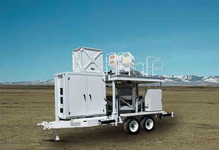
The Close-In gimbal can be configured with a ruggedized, towed trailer system customized for operations at multiple sites.
Stabilization:
The Close-In system can be configured with stabilization hardware and software that allows use of the system on a ship or other moving platform.
Operator Stations:
Photo-Sonics offers a variety of remote operator station configurations including a full-size console, a compact console suitable for mobile command vehicles, and a desktop configuration with large touchscreen monitors displaying multiple images from various sensors on the tracking systems. The compact console is available in a standard 19” rack cabinet or easily-moved transit cases.
Argus Control Software:
Photo-Sonics provides all the functionality the user would expect of an advanced TSPI tracking system with our Argus control software. It provides a single interface for the tracking pedestal, sensors, auto-tracking, ranging devices, calibration, target simulation and diagnostics of the complete tracking system. We have simplified control of the system via an intuitive touch screen graphical user interface (GUI).
The standard Argus application can control up to 10 sensor stations; including fixed focal length and zoom lenses, focus tables, ranging devices, and single- and multi-gate auto-trackers. The close integration of the system allows a single operator to retain complete control of all aspects of a complex and highly capable tracking system from a remote location.
We have achieved the highest TSPI accuracy of any optical tracking system manufactured today, in part, because Argus simultaneously uses a combination of automated star calibration and turn-and-dump calibration. Using these methods of calibration, you can achieve post-mission accuracies of 50 micro-radians and better. When multiple mounts are used, with the Photo-Sonics Multi-Station software, you can achieve real time accuracies between 50 to 100 micro-radians.
Communication:
Photo-Sonics can support a variety of connection methods between the tracking mount and the operator station. One option is via a single-strand, single-mode “dark” fibre optic cable, which allows for separation up to 20 kilometres. A total of four video channels and two Ethernet channels are multiplexed on the single fibre. Other supported interfaces include shared networks and point-to-point microwave transmission links.
Optical Tracking Systems Product Menu : Close-In - Mini-Sextant - Fly-Out
For more technical details, contact a member of the team at Photo-Sonics International Ltd.